![]()
|
Digital Command Control
Digital Command Control (DCC) for model railroad operation is a standardized means of superimposing a coded signal on an alternating DC voltage on model railroad track. Each model locomotive has a tiny electronics package with a unique address; the "decoder" decodes control information (which direction to move, speed, sound, headlight on/off/dim, etc). There can be many other devices in addition to moving locomotives that receive and act on control information. With DCC, bulk encoded voltage is distributed to all track and to any other accessories. An accessory such as a "stationary decoder" might use both the voltage (to move something) and the encoded information, or just use the encoded information. DCC-Unfriendly Turnout Servo Control6/16/11: Rev 1 and 2 built and tested, Rev A being prepared PIC microcode being worked on The beginnings of my home layout is a hidden yard that includes 16 track switches (turnouts). When I originally purchased materials, I did not anticipate moving to DCC (this was in the early 90s...DCC already was standardized, but DC control was still around). The 16 track switches were what is called "DCC-Unfriendly". I didn't want to scrap and repurchase, and the modification to these was unattractive too. Given the number, I didn't want to spend much per turnout to control these. I worked on a mechanical method that used an inexpensive slide switch to control power to the turnout frog and points, with model aircraft control rod technology to remotely mechanically activate. This looked like there were still some problems, and this took a lot of hand fabrication to make and install. Cost was still around $5-$10 per turnout, and there was no electrical remote indication function. While I was away from model railroading (early 90s to 2011), really cheap model aircraft radio control servos became available (under $3). Many modelers used these to remotely move turnouts. However, I still had a frog power switching problem for my "DCC-Unfriendly" turnouts. I didn't find any solution that I liked (especially mounting microswitches on the servo to do the power switching: for both cost and under-the-layout mechanical installation complexity). I did find a single servo control project (by Paco Cañada in Spain) that was close to what I wanted. I modified that design to use 2 power switching relays rather than one (this allows break-before-make power switching: the turnout frog/points are deactivated, the servo moves the turnout, and the frog/points are then reactivated with the new power source). It's still appropriate to use the #1156 bulb technique in series with the frog to protect everything up the chain from a derailment short or other short across the DCC track power. Of course, a "DCC-Unfriendly" control will work just fine with a DCC-Friendly turnout as well. At most, there is only the cost of the additional relay (the transistor relay driver element adds about 10 cents, a relay between $1.65 and $2.14). Thus my very first small printed circuit board project. Here are the design files available for the DCC-Unfriendly Turnout Servo Control:
The miniature SG90 servos need a mounting bracket to readily mount underneath the turnout. Here is a PDF of a bracket, and a PDF of a template that can be used to cut a 4"x10" stock aluminum sheet into 15 brackets. The bracket provides a fulcrum hole; music wire connects the arm of the servo through the bottom of the layout and directly manipulates the points (no other mechanism needed). You'll need 2-56 hardware (1/4" bolts, lock washers, nuts) to bolt the SG90 servo to the bracket (you'll probably need to drill out the mounting holes on the servo with a 3/32" 2-56 clearance hole). The brackets are set up for #4 screws to screw the bracket into the bottom of the layout. The aluminum sheet (0.032 thick by 4" x 10") ought to be readily available in your local hardware store (look for the standard "K&S" brass, stainless, and aluminum strips display stand). Print the template and make sure the outline is 4" x 10" (for me, this just required telling the printer to not try to scale the PDF to fit the page, but to print directly). Cut the template out. Using rubber cement or similar adhesive, glue the template exactly over the aluminum sheet. Center punch the holes and drill. Using something like an abrasive cutoff disk (with eye protection!!!), cut the brackets into individual pieces (there is plenty of slop in the template for the cutting process, by plan there is no precision needed between the brackets). I used a sheet metal nibbler tool to then rapidly cut out the notches for the servos. Using the bend line as a guide, bend each bracket (I just put the flat bracket into a small vise at the line, and pushed over to form the 90 degree bend). Peel off the template paper, and you are ready for mounting. The aluminum sheet cost me $1.89 plus tax locally, making each bracket cost about 13 cents - not including the 2-56 bolts, #4 screws, or the music wire (0.025 if you want springiness, 0.047 if you don't). I can't take any credit for the bracket, only for delivering adhoc fabrication assistance (at least, delivering what has easily worked for me).
6/22/11: Rev 1 being built and tested 8051 microcode being worked on project description to come Turnout Servo Control Panel Button6/12/11: Rev A out for fab It occurred to me in the middle of one night that I could use the 5cm x 5cm printed circuit card format and split it into 4 quadrants, and make really little circuit cards (2.5cm x 2.5cm) that would greatly ease the construction of a yard control board. The Panel Button project has connections to go to the "Button" input and "State" output of the DCC-Unfriendly Turnout Servo Control, and is designed to be soldered on to the back of a pushbutton, which in turn is mounted on a panel. The card provides transistor switching of the single "State" signal to turn on either a Green Normal Position LED or a Red Reverse Position LED. Three quadrants of the 5cm x 5cm board form instances of this; the fourth quadrant is a little 5V regulator to provide 5V to multiple Panel Button cards (this quadrant has a single mounting hole to affix to the panel). [I'll have to manually separate the quadrants after I receive the fabricated boards.] 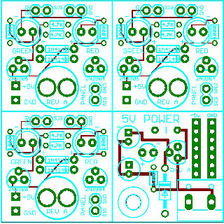
The LEDs and the push button can be soldered from either side of the button quadrant card, so "left green" or "left red" LED order can be done for panel location requirements. There is also provision for pass-thru of the "State" signal to go to a DCC feedback product (a panel is a great place for such feedback, as all feedback signals are already aggregated in a small area). Parts cost for the 5V regulator quadrant is a little over $1; parts cost for a button quadrant is a little over $1.40 (and that includes the push button!). Printed circuit board cost per quadrant is a mere 35 cents! [of course, labor to separate the quadrants and labor to assemble is the hobby element!] Technically, this project is useful for other tasks too - since it provides an unconditioned switch closure and a TTL status display. The 5V regulator card has general workshop utility as well. Here are the design files available for the Panel Button:
|
![]()
Copyright ©2011-2012, E. Kroeker. All rights reserved. Contact with remarks or questions.